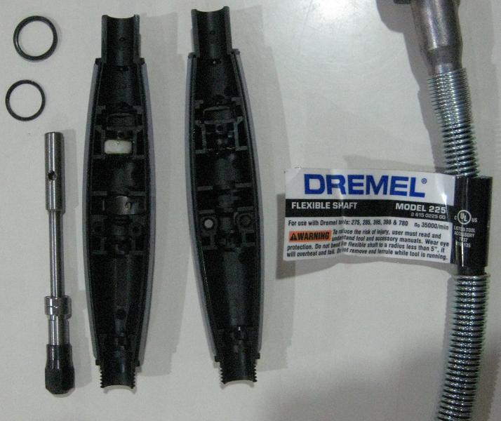
So I’m in the midst of designing a proper high speed spindle for my positioning table. The stock dremel spindle is horribly inaccurate yet their collets and miniature chucks are surprisingly very accurate. I Figured I would take one apart and see what makes one spin. I chose to take the flex shaft apart as I never use it, it gets quite warm and I require the use of my dremel during this project so its staying together.
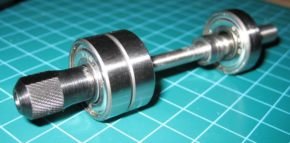
You can see in the pictures that the spindle rides on two itty bitty bearings but they are not press fit, actually they are quite loose and have a bit of wiggle to them so they are not going to be used. I have some 22x8mm AC bearings from VXB.com as well as some regular 22x8mm ones that I will be using for this project.
My plan is to turn down a tiny spindle sleeve to press the flex shaft spindle into and then press fit the bearings over top that sleeve. Theirs not a whole lot of room to play with here so its going to be a test on how bad I suck on the lathe. Unfortunately my lathes motor is still incomplete so I wont be doing any real building for a few weeks at least.
Well onto the projects Goals:
1: Very high speed
The machinery handbook recommended a surface speed for aluminum as: Drilling: 400, Reaming: 300, Milling: 600
The calculation for spindle speed is:
RPM = (4 x SFM) / Diameter
Given this data my spindle must be able to produce a maximum RPM of:
(4 x 400) / 0.031 = ~52,000 RPM
This will give test best results for my most commonly used PCB drill size.
2: Very high accuracy
My goal is <0.001” (1mil) runout so I can to boards with 0604 components without worrying. The positioning stage has 0.0005” accuracy so having a spindle any less accurate would be a waste.